Alvin
-
Posts
108 -
Joined
-
Last visited
Content Type
Events
Profiles
Forums
Gallery
Everything posted by Alvin
-
Solenoid if I remember right. Haven’t touched that ever.
-
My guess would be that the fan requires 5A at 12VDC max then the solar panel needs a minimum of about 80 to 100 watts to run it at high speed. Perhaps 20 watts at low speeds. This is assuming about 21 volts output in full illumination and a voltage regulator to get this down to the voltage needed by the fan. The losses are mostly in the regulation. As daytime slips away Vout will drop.
-
You want things to work as well as they can work? Or just kinda work lol. if I wanted to drive my Odyssey to Alaska, I would be very grateful to have things working quite well. I would probably even go to great lengths to point my solar array perpendicular to the sun. No harm knowing the rocket science details.
-
You and I are in agreement. My comment was actually directed to Linda, and she not wrong; she makes a good point. But she doesn’t consider the case of getting the most efficiency out of a small under-sized RV solar array: The traditional method of running solar power through a charge regulator into a battery and then out of said battery and finally to the fan motor Involves several power losses. 1) charge convertor losses 2) battery charging loses (all batteries have internal effective resistance) 3) battery source resistance, and 4) device motor losses… ignoring wiring copper loses. To get the most out of available solar panels, it would be desirable to direct connect the solar panel to the fan… if possible. From a losses standpoint the best solution would be a dc-dc regulator but those are $50 and up, so I recommended an LDO (low drop-out) voltage regulator for the solar panel direct connection. Most of the dc-dc power supplies I design are 85% to 93% efficient where efficiency of the LDO will be somewhat worse. But nothing beats the price of an LDO.
-
I design power supplies for USA defense. The question was not whether the solar panels were connected in typical fashion. The question was about how to keep the voltage presented to the fan from going as hot as 13.6V…. Which easily happens with solar panels directly connected to a device. Yes most people use regulated battery voltage to run the 12VDC RV appliances… and those batteries are charged from any number of sources… vehicle engine, generator, shore power, … you could use hamsters in cages if you want. And if you want to charge your house batteries with solar, then you would use a solar charge convertor as you said. But if somebody wants to forgo the charger and connect the panels up directly, that’s doable too with a voltage regulator.
-
I would need to know the current requirements of your fan, but it Looks like some Maxxair 12VDC ceiling fans require about 12V and 5A. You could go with a large linear voltage regulatir such as Analog devices LT1084CT-12#PBF. DIGIKEY has them for $11.22. You’ll also need a couple of low cost caps (see the datasheet).
-
I need to know the current requirements of your fan, but it Looks like some Maxxair 12VDC ceiling fans require about 12V and 5A. You could go with a large linear voltage regulatir such as Analog devices LT1084CT-12#PBF. DIGIKEY has them for $11.22. You’ll also need a couple of low cost caps (see the datasheet).
-
Thank you and what a great set of instructions to get me started. As luck would have it, I inherited my Father’s set of gauges for recharging ac... i don’t know how to use them but will do the research.
-
Had great ac in our 1989 Odyssey until just this year. I’m going to be looking for the obvious before I take it to someone to do an expensive leak check and recharge...because it went down after the long cold winter and seems kinda sudden. I’m ‘about’ to look at the ac compressor belt and electrical connections. We did call an ac shop who said they don’t work on 89 toyota trucks because they’re too old. They also said it would need a conversion.
-
Battery charging is all about the internal resistance of a given battery. When the batteries are new, they have lower resistance...charge faster. This will change over time. Not sure you have a problem.
-
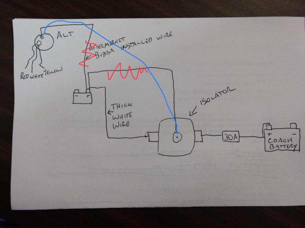
I still think I’m right...thought I’d add two more schematics I have on hand to add to the confusion. I think the part is an Isolator and not a solenoid. I have one in my 89 Odyssey.

-
I marked up your drawing. Get rid of the two wires with red zigzags over them. Connect, using one heavy peice of alternator grade audomotive wire, the connection shown in my drawing in blue. You don’t want any splices... it should be one heavy wire between alternator and isolator. If you splice thats a future breakdown due to corrosion.
-
Linda, that is exactly right. A diode is a semiconductor which only allows positive current flow in one direction. An isolator is a device with two back to back diodes built in, and the alternator is the source of this ‘positive’ current, supplying current when the engine runs. The alternator connects to the isolator junction of both diodes and supplies charging current through each diode, one to the house battery charging system and the other to the vehicle battery. When the alternator is not supplying current (when the vehicle engine is not running) then the house battery can’t short to the vehicle battery and visa-vera due to their respective one-way diodes in the isolator. It means you can turn off the engine safely with each system, vehicle and house, remaining separate.
-
The schematic Derick up North provided is correct. The idea is the alternator charges both the house and engine batteries when the vehicle engine is running...or when the alternator is turning. The back to back diodes in the “isolator” keep the two systems, engine and house battery, separate except for alternator charging.
-
So...that;s not a soleniod is it? Looks like the house/cab isolator. A back-to-back automotive diode.
-
dd17dsi.pdfSuburban_Furnace_NT-16SE_NT-20SE.pdf dd17dsi.pdf these manuals are for the furnace in my 89 Odyssey. I think the part you need is the “electrode”. Using these manuals i was able to find a new furnace motor on amazon.com.
-
I almost put solar panels on my odyssey last summer, and these Li+ would compliment that well. The smaller size looks much easier to deal with too, higher power densities naturally. Always wanted to parallel my house battery... this may be the best way to accomplish that in about the same space. Nice find. Yeah, +1 on the do-it vote.
-
Here in Utah, we see winter temps as low as 0f. While winterized, you could always either keep a remote temperature sensor in your rig, or bring in the batteries if it gets much colder. The specs are indeed impressive.
-
Maybe for the house batteries, as long as you stay within Li+ battery temperature limitations. -4f to 110f. Not sure thats good enough.
-
Wonder if blowing into the horn would cause 12V to appear at the terminals? Sorry couldn't resist.
-
As Buzz Lightyear said to Woody, "You're mocking me, aren't you." lol. Kidding. I knew I should have kept quiet. My Odyssey is a 1989 and it would be interesting to compare the differences to the 1978 truck. Have been tempted to put in an SR-5 dashboard.
-
I've been in the business of designing ruggedized equipment for military and industry for almost 30 years. Over the years I've worked with dozens of EE's and dozens of ME's. There is a "style" employed by the ME's that is very recognizable which doesn't include the "tricks" of the trade that the EE's know to use... ME's are great and they're very talented, but when it comes to schematics, they do tend to spagetti wire everything all over the drawing (see schematics here as a good sample) while the EE drawings tend to be compartmentalized into multi-page hierarchical "snippet" drawings with a much heavier reliance on notes to indicate attributes and parameters such as wire type, colors, harness definitions, etc. Many of the ME's are car guys naturally and know tons and tons, but their schematics reflect more of a mechanical reliance on visually seeing the wire. Fewer port connectors, fewer off-page connectors, no "multi-channel design" (one page repeated over and over again for similar sub-circuits), and NEVER using a harness definition (this takes a bit of knowledge about the schematic tools, which can cost over $100,000.00 per license (Mentor Graphics with full blown extras) but not always... $6K will get you a good license of my favorite tool "Altium." I didn't mean it as any slight against ME's. Just that the style is so much harder to read. Would love to be able to include a recent sample but contracts prohibit that. I've included a link that illustrates some of the concepts. http://www.altium.com/files/altiumdesigner/s08/learningguides/tu0112%20creating%20a%20multi-channel%20design.pdf An optimal schematic might include 6 to 20 parts, all related to a given function, on a single page... with those pages connected at a higher level. Anyway, that's the flavor. How do you think that EE's are able to design chips with literally millions and billions of parts? They certainly don't create a schematic. Not anymore. Instead, they rely on the methods I've outlined above. Again, just wanted to say "yuck" lol
-
As an electrical engineer, I draw circuits all day long. Just wanted to comment on the sad state of schematics drawn by mechanical engineers who feel the need to put everything in the vehicle on one page: We have this thing now called "Hierarchy" which allows us to place the entire circuit in a box at the top level. In this box, you would find a very rough block diagram, connected with live representations of harnesses. This really has only been the last 10 years when the software is advanced enough to do this, but you can keep dropping down through the hierarchy as deep as needed. For complicated systems (i.e. vehicle) we bust the schematic up into a working list of systems connected by name, or connected by harnesses. Sure cleans things up. It almost hurts to go back and look at the mess of unneeded lines used by ancestors in the days when schematics like this were needed. Okay... my comment didn't contribute squat... I'm glad we don't do it like this anymore.
-
Fred Flinstone used a large toucan bird horn mounted on the drivers side mirror, and I remember an attention getting honker horn used by Rodney Dangerfield in Caddy Shack. You'll have to trace it back as far as you can, find out where the last known good connection is, and if you can't find the broken wire, run another wire to the horn from the last good location where you can measure voltage. You may need a helper to push the horn down as you measure for 12V, or use an ohm gauge to ohm it out.
-
No scanner? Digital camera images of documentation work too. We take picture of notebooks and whiteboards at the office.