yestertech
-
Posts
13 -
Joined
-
Last visited
About yestertech

Recent Profile Visitors
188 profile views


yestertech's Achievements
")
Apprentice (3/14)
-
 Rare
Rare
-
 Rare
Rare
-
 Rare
Rare
-
 Rare
Rare
-

Recent Badges
-
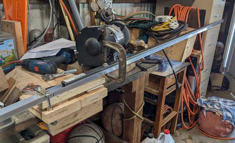
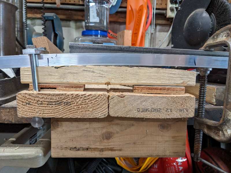
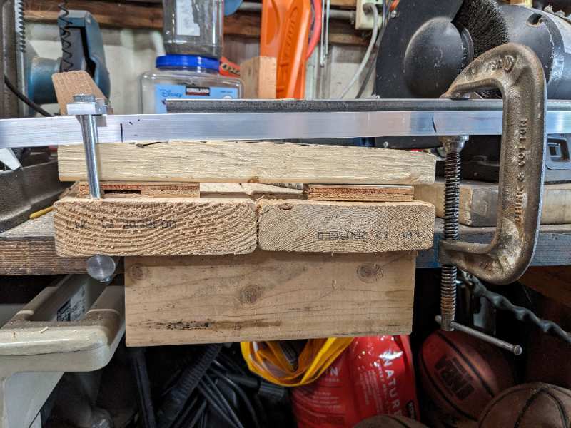
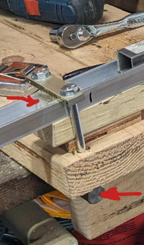
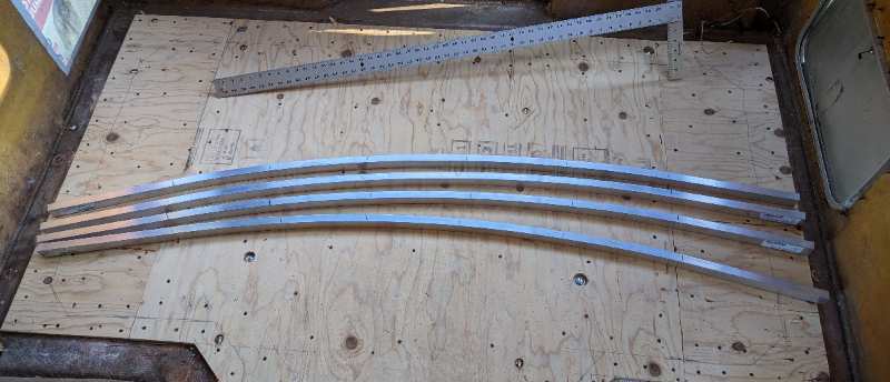
I used six-foot lengths of channel 1.25" wide, 0.75" tall, 1/8" thick, purchased from onlinemetals.com. I contrived a BFD (Bending and Forming Device) to make the bend along the four feet in the middle of the six. Here it is in all it's glory, screwed down to my fixed wooden workbench in my disgustingly cluttered shop. Note that there is a long chunk of 1" x 1" square steel tube sitting in the channel. A C-clamp constrains the bending stress to the region between it and the fixed clamp on the left. The piece under the channel between those two clamps (form block) is where the bending happens when I push down on right end of the steel tube. I would push down until the channel just touched the end of the curved form block. Since the bend region is about 4' long, the bend is made in five sections, by re-positioning the channel in the BFD. The clamp at the left has a chunk of aluminum (arrow at upper left) that contacts the base of the channel, not the top of the legs. The bolts thread into a piece of round bar (arrow at lower right) Here's a shot of the channel prior to a bending operation and after I wanted a final radius of 110", but had trouble accurately predicting the springback. I didn't want to bend it too much, since my BFD only works in one direction. So I had to sneak up on it. I had to re-make the curved form blocks over which the bend happens four times before I got it close enough to my target, and the radius of the last one was 57". I suspect that if had been able to bend it to the right radius in one pass, that number would have been different. I suppose had I bought an extra piece of channel I could have done some experiments to arrive at that number, but I didn't want to spend money on scrap to do so. In the end my process was at least repeatable across the four beams I made, so the job was done.

-
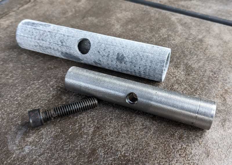
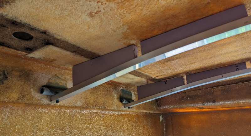
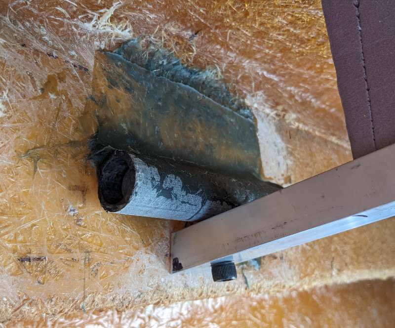
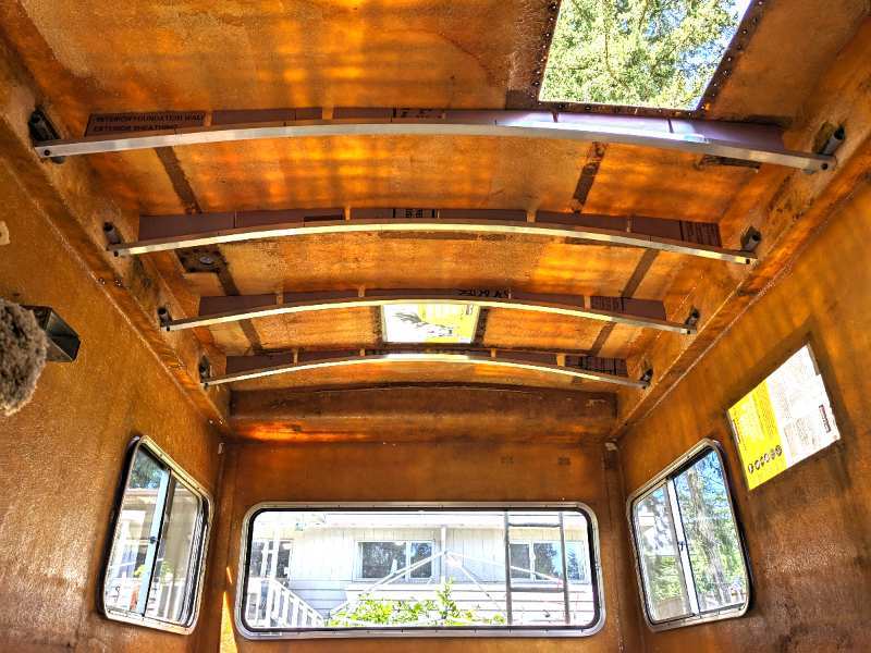
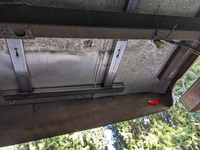
i added some support for the droopy roof of my Sunrader. I used aluminum channel, formed into arches, and supported by 5" hunks of 1" diameter fiberglass tubing attached to the hull using Evercoat Kitty Hair, a rlong-strand glass fiber loaded epoxy compound. I machined some "nut bars" that fit inside the tubes to which the beams attach with 5/16-18 bolts. Chunks of 1" thick Foamular styorofoam insulation fill the gap bewteen the beam and the inner surface of the roof.I I don't expect to be tromping around on the roof, but this is a lightweight solution to the droop. Plenty of space for insulation, lights, whatever. The beams can be easily removed for adjustments, or the fiberglass work that still needs to be done to fill the vent hole where the bathroom was. formed beams: end support: part detail blocking:
-
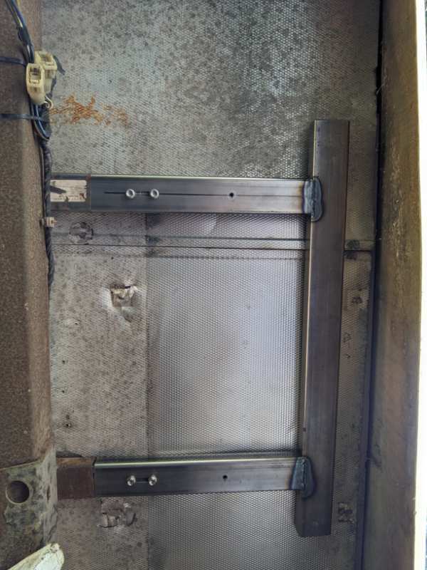
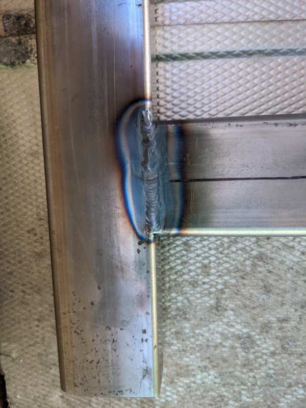
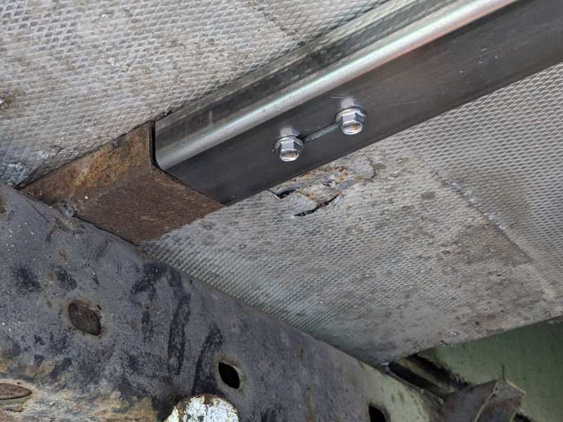
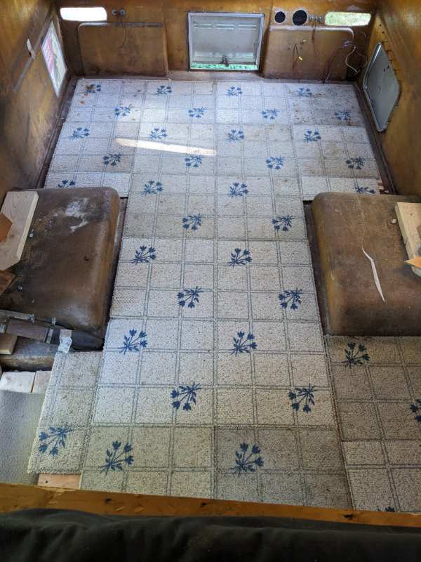
Finally - what caused the droop in the first place? Other than the fact that the composite floor lost its structural integrity over time, I think the manufacturer could have spent a few more bucks on steel to support it. So I added some. The cross beams are 1" x 2" rectangular tubes. There's one near the rear edge, and another a bit behind the wheel wells (my Sunrader is an 18' model - I don't know what's underneath the 21' ones). I added another similar tube. And then I build a "wing" for each side from similar material. What I got has 1/8" walls, I realized later that the tubing on the Sunrader is a bit thinner. I was able to slip the new cross piece in while the coach was elevated, and spliced the wings into it and the existing one behind the wheel wells with 8" pieces of 1.5" x .75" rectangular tubing. These splice pieces slid into position once the wing was positioned, and screwed in to secure them. Only then did I lower the coach onto the chassis. Overall, the coach/cab is 1/4" higher than before. This is negligible, and due to the thicker insulation. The floor is 7/16" higher, which cuts into the headroom a bit but gives the floor much firmer feel than before. The droop is almost gone. I think a bit remains where the water heater was, but this is not really a walkable zone anyway, so I'm still satisfied with the outcome. Just for laughs, I put down some old carpet tiles salvaged from a kitchen remodel. I haven't decided yet what to put on ultimately. Next up - the droopy celing. The wing under the right rear the wing from a snail's eye view. Rear is at the top - the sticker is stuck to the new cross beam Where the wing meets the existing cross tube I got some welding practice in. I'm a bit rusty. These old carpet tiles don't look half bad!
-
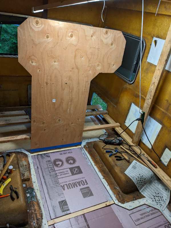
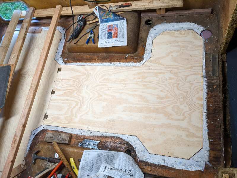
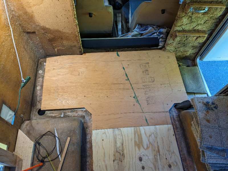
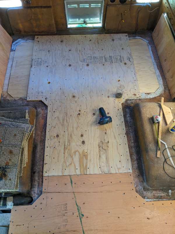
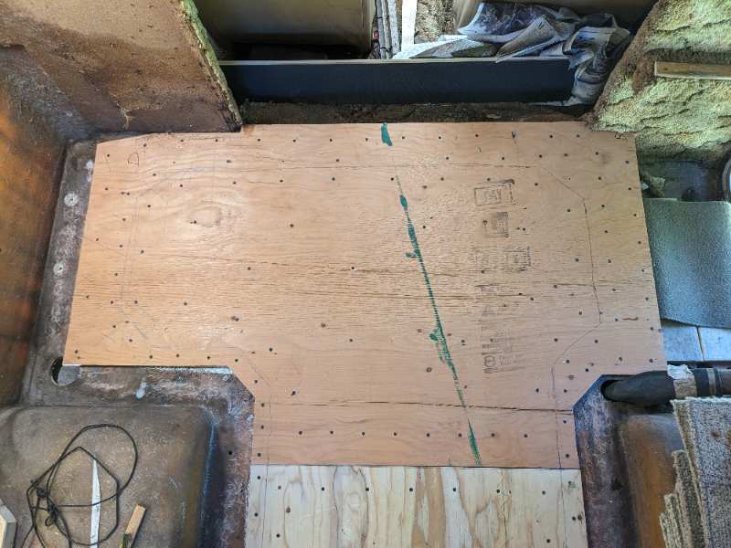
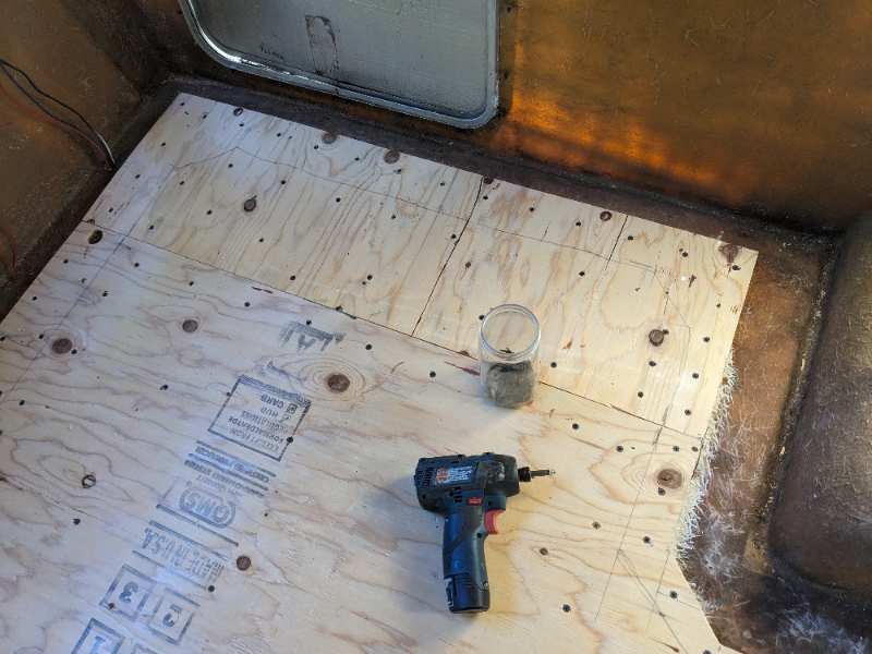
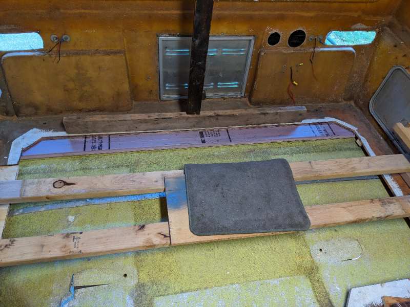
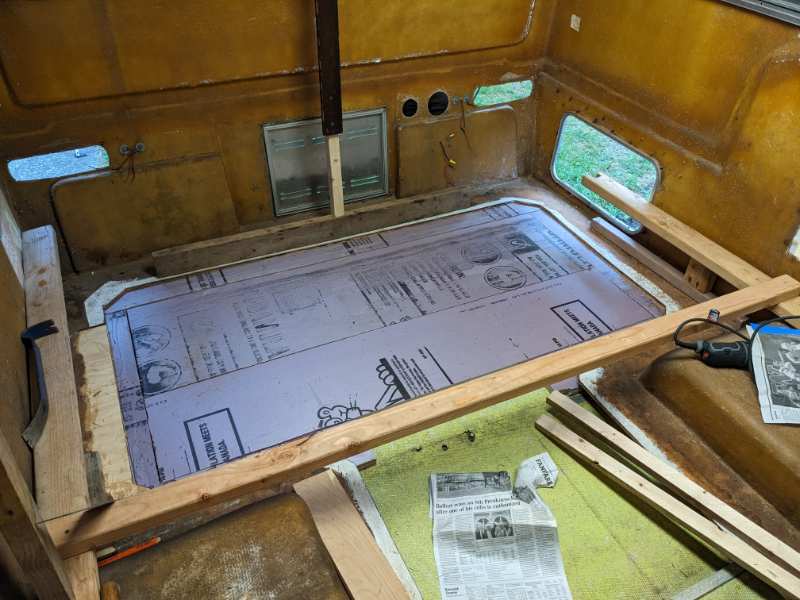
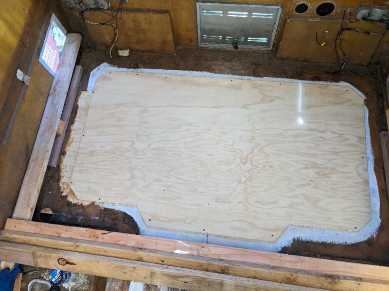
Once the insulation was down, it was time to replace the 3/8" plywood pieces. While these had been cut out beforehand, the cut in the floor had changed some so some trimming had to be done. Since I was gluing them to the insulation with the 3M 78 contact adhesive, I had no chance to re-position them if they went down askew. So before I sprayed the adhesive on I screwed hinges to a straight edge. Tilted up, I could spray the adhesive on both surfaces and just flop them down five minutes later. I'd cut a filler board 1" thick at the junction where the two pieces to screw the hinges into. Both pieces of 3/8" plywood went down that way, and were now more or less flush with the old wood around the perimeter. But not quite, of course. So a top layer of 7/16" plywood went on top of the whole schmear overlapping all the cracks between the various pieces of 3/8" material. This I put down using a combination of construction adhesive (around the outside where it had to stick to fiberglass resin), wood glue (where the top 7/16" plywood met the 3/8" plywood), and a bucketful of sheet-rock screws to hold it all together while the glue dried. One more step before the coach with its new floor can be lowered back down to the chassis ..... The front piece ready for glue and lowered into place, glued to the foam beneath. The rear piece was similar. The top and final layer over the front And the top layer over the rear Last but not least, the outer wings over the formerly droopy zones behind the wheel wells.
-
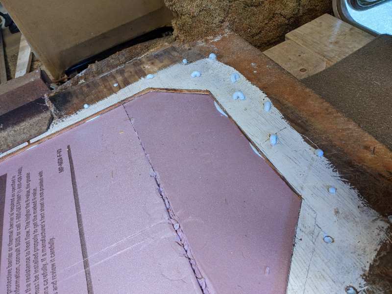
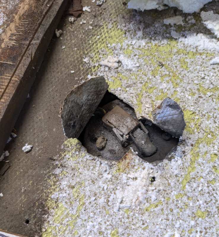
The next step was to re-install the insulation. First I had to prep the surface of the aluminum sheet, which at this point is just kind of dangling in the margin between the frame of the truck and the coachwork. I used a paint scraper to clean off as much loose glue/foam residue as I could, and then went after it with a stiff scrub brush and a detergent solution, after which I rinsed it and let it dry thoroughly. I had planned to replace the 3/4" foam with new 3/4" foam but had trouble finding any locally. What I did find was one inch thick "Foamular" material in 4' x 8' pieces. This had me stumped for a while but eventually I realized that since I had the coach/cab off the frame I could just raise it by 1/4". The bolts that held the cab on had that much extra length. I cut pieces of the foam to fit under the flanges first, then cut larger pieces for the center portions to glue to the aluminum. I used a 3M spray adhesive "78" designed for foam and bought it through Amazon. Ultimately I went through four cans of this stuff. It was rather spendy, but since adhesion is key to a durable composite, I figured it was worth it. It sticks to the aluminum, foam, and new plywood very well. It sprays out like snot and you can expect the nozzle to clog now and then. Also, it's an "industrial" product, so I wore nitrile gloves and a respirator when using it. It's a contact cement, so you spray it on both surfaces, let it dry around five minutes, then press the pieces together. I found when I pushed the aluminum up from below, it would stick to the foam instantly and stay there. The other downside of this spray goo is that it was tough to reliably spray the underside of the existing-wood flanges. In some area I used a caulk-gun type adhesive called PL-300 that I bought at my local box store. I drilled holes in the flanges and squirted in portions after I'd slid foam chunks underneath, then applied pressure from below to squeeze out excess. Here's the rear margin piece in place. Notice the vertical beam pressing down on a 2x4 to eliminate that pesky tilt until the adhesive took hold. In this shot you can see where the ends of the steel support beams had punctured through the aluminum sheet at the base of the old floor. Stay tuned for details on how I dealt with this. Once the edges are in, the central portion is easy to glue in after pressing the aluminum up from below Here's a shot of the alternative caulk-gun type PL300 in action (before the excess was removed)
-
The front section went pretty much as the rear. I discovered that a connector on the top of the fuel tank had punctured through the aluminum sheet. I made some spacers and lowered the tank by 1/2" Here's the center section cut loose The foam removal from the center part between the wheel wells. forward left part, under where the bathroom was Forward right portion Here's the connector on top of the fuel tank poking through the aluminum sheet.
-
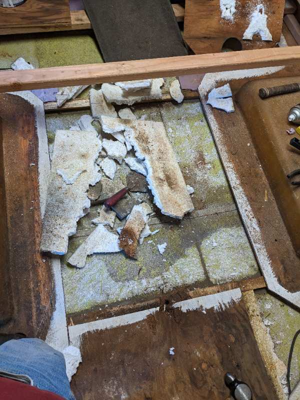
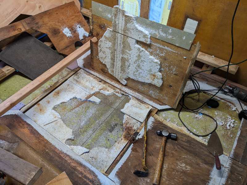
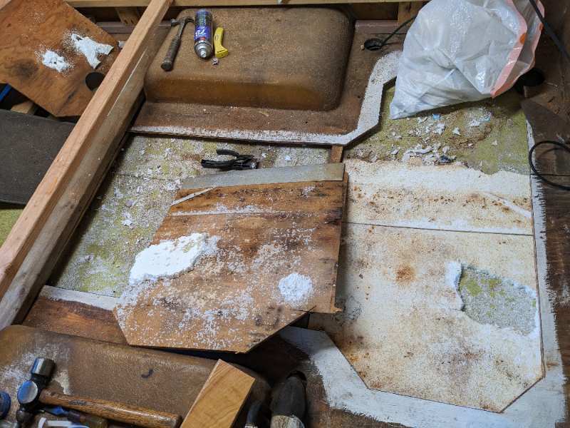
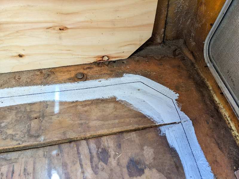
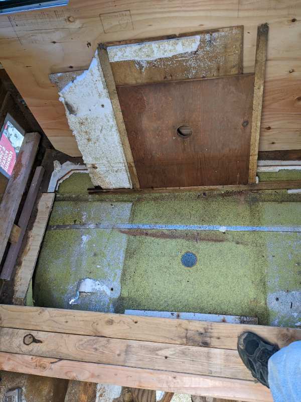
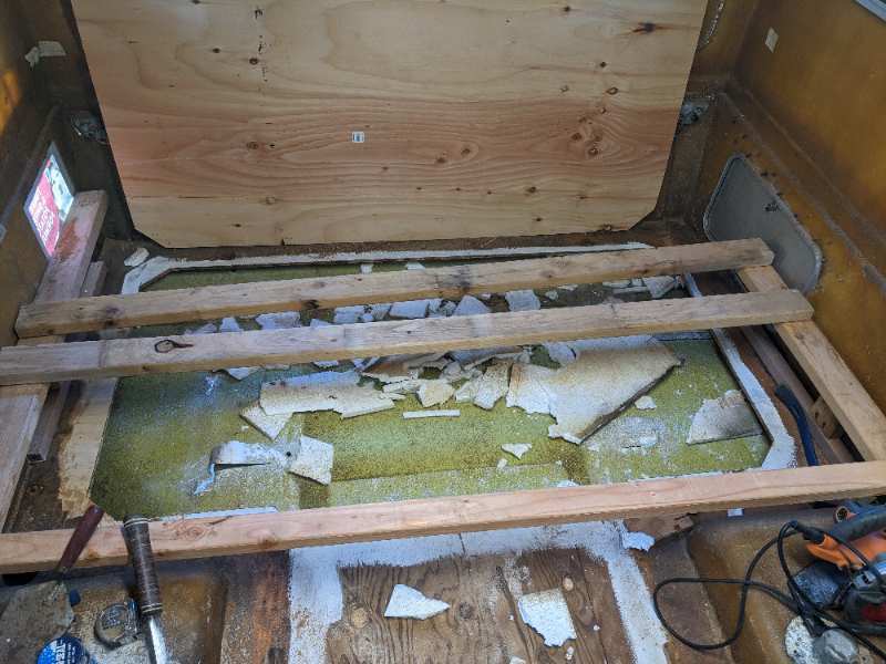
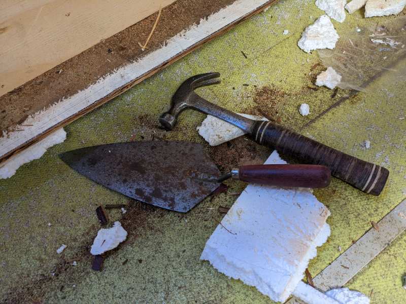
Now the scary part - Demolition! Since I had decided to leave a margin around the perimeter, I had to decide how much to replace, and how to cut 4' x 8' plywood hunks to replace it. I cut out the rear piece first and painted a crude white line on the existing floor where the edge would lie. Then I positioned the new wood on the old and traced a line onto the old. This is where I would cut through the old wood, leaving about a 6" margin around the edge. Prying up the old floor here, I found that there was a large square piece of 3/4" plywood around where the dinette table once mounted. I had to get ALL the 3/4" foam out, and an old pointing trowel and a hammer did the trick around the perimeter. For the most part, the old adhesive had failed. New chunk pre-positioned to trace cut line detail of cut line traced onto white paint stripe cut line complete Rear portion cut loose and lifted up. foam removal mess Foam around margin flange being removed
-
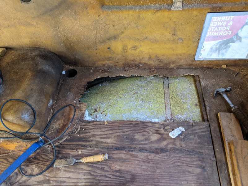
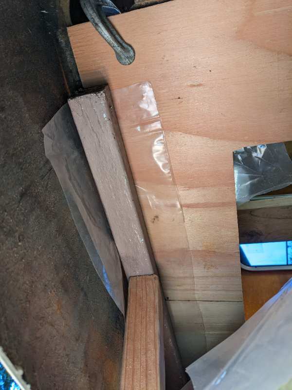
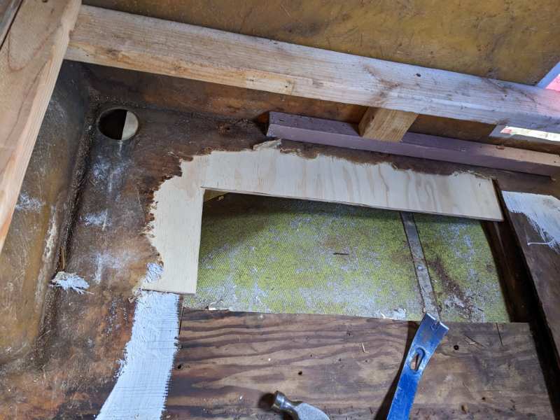
The next step was to remove the one really rotten bit where the water heater had been. The rot went out all the way to the fiberglass, so I had to chisel what was left off the underside of the fiberglass flange. This wasn't much fun, and I didn't want to have to do this all the way around the whole perimeter of the floor. This was the only spot where the old plywood epoxied to the fiberglass coachwork had disintegrated, so I just wanted to replace the plywood flange. The inner edge of the new wood will be trimmed in a later step. These pictures show the Styrofoam already removed, and you can see how the aluminum is loose underneath. In general the adhesion between the aluminum and Styrofoam had failed, so it wasn't hard to clean the loose material off the aluminum. Having the extra inch or so of vertical clearance after raising the coach helped here. I used epoxy to attach the new wood to the underside of the fiberglass flange. Clamps from above and a support below held the patch against the flange until the epoxy had cured. The rotten part cut out new piece clamped in place, from above and from below Final result
-
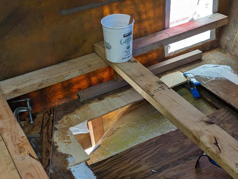
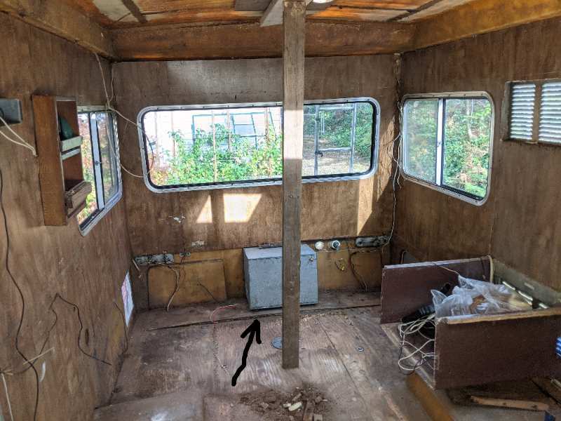
Since I had to work from above but could't stand on a floor that I was removing, I had to build a scaffold of sorts. These pictures show what I cobbled up. Basically it's some scrap 2x4s bearing on the outer flange of the coachwork. One 2x4 is screwed from left to right to hold the rails in place, and a couple of others are just laying on top so that I could move them around to where I needed to be. I also used a chunk of plywood on top of a pair, positioned as needed, that I would perch on and re-position as needed. The rear part of the "scaffold" in place right side. The vertical board supports the droopy roof (another project) A support along the sill edge Some cobbled blocks in front of the right wheel well
-
I've started a new thread with a description of my floor repair process here.
-
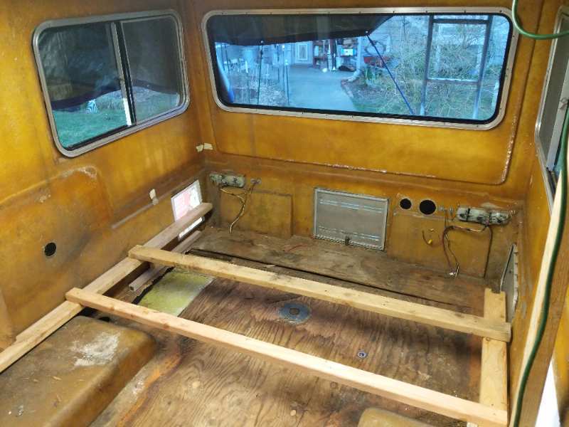
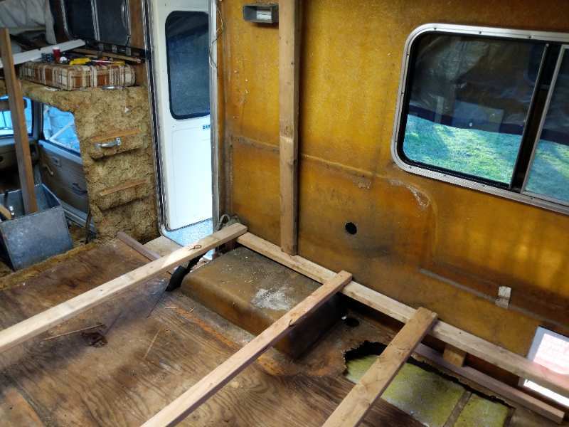
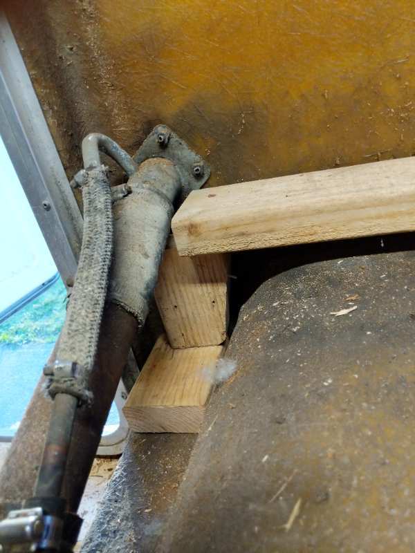
I bought a decrepit 1980 18 foot Sunrader in August of 2022. I live in the Pacific Northwest, where this had been sitting outdoors its entire 42 years. The weather had taken its toll on the interior. By the time I'd completed removing rotten bits I was out to the fiberglass. I wasn't surprised by this - the signs of advanced decay were evident when I bought it and I didn't pay much for it. It had been sitting for a few years but, being a Toyota, I was able to get it running and drive it the ~60 miles home. Once I had the cabinetry and carpet out it was clear that this project had to begin from the bottom. The floor was springy and far from flat. The floor is about nine feet long, and the main piece of plywood is only eight feet long. The manufacturer put the seam at the rear, and there was an odd step at the junction where it once met up with that last foot. (pic 1). The rear edge of the fiberglass coachwork was sitting on the bumper (pic 2). The steel beams behind the wheel wells between the frame of the truck and the floor run from left to right and are only about four feet long, and the rear one isn't far enough back. So the support of the coachwork depends on the strength of the composite floor construction. The weight of the coachwork bears down on the edges, but the steel support beams are well inboard from there, so they are cantilevered out. In the case of my 1980, the floor is composed of a thin aluminum sheet on the bottom, 3/4" inch of plywood Styrofoam, and 3/8" plywood on top. There is no 1/8" plywood between the aluminum and the foam, as later models are apparently built. The aluminum/Styrofoam/plywood sandwich is a reasonably strong composite construction so long as the adhesive between the layers holds, but once it doesn't - all hope is lost. That's what happened to mine - allowing the coach to sink around its supports, resulting in the gap where the two pieces of plywood once joined flush, and sunken areas behind both wheel wells. The ends of the steel beams had punctured the aluminum and the floor he deformed around them. The junction between the rear of the eight-foot plywood floor and the rear piece had popped open, and that rear edge of that rear piece, still attached to the fiberglass, had sunk well below the support. The front edge levered up, resulting in the gap seen in pic 1. I suppose the "right" way to fix this would have been to remove the entire fiberglass coach, set it up on some kind of stand, cut all the plywood and build a new floor in from scratch, working from below. But I couldn't see myself taking that on. I didn't want to remove the coach from the cab, either. But to fix droop I had to raise the coach off the truck's frame enough no only to eliminate the droop, but to give myself enough space to replace the bulk of the floor from above. I found that the coach is attached to the frame in several spots: two carriage bolts at the rear edge, two more just aft of the wheel wells, three in a line in front of the wheel wells, and six stock Toyota mounts between the cab and the frame. I fought loose the rusted nuts holding the floor to the frame and the six mounting the cab. I then jacked up the frame of the truck, placing it on jack stands and shimming until it was level. I removed all the nuts except the front two in the front side of the front wheel wells. Here I backed off the nuts until they were just engaged on the bolts by a few threads. Then I jacked up the coach OFF the frame, pivoting on those front two bolts. I didn't want to lose the registration of all those holes, which would have been a nightmare to re-align. I learned later on that the three bolts in front of the wheel wells attached a length of angle iron that is not attached to the frame. It wound up lifting with the floor and hanging loose. The heads of the two carriage bolts on it's ends are glassed-in to the fiberglass wheel wells. The center bolt was the only one i had to cut out with a fiber wheel as it was just too rusted to remove. The last pic of this first post shows a chunk of 2x4 supporting the coach on the rear bumper after lifting the coach. I had another piece of 3/4" lumber in the stack when I had it fully jacked up into a working position. Once up, the aluminum sheet did not contact the frame any more. The floor at this point was only supported where it was attached to the edge of the fiberglass coachwork. At this point the floor inside was VERY soft, and i could only walk around the edges or on the wheel wells. Here's the main "before" pic, showing the step between the main floor piece and the rear edge. Here's where the coach is sitting on the bumper. Good thing the bumper was there to limit the damage! After jacking the coach, I put this block in place to hold it up. Later I added another 3/4", for 2 1/4" total
-
Ok! I'll start a new thread very soon
-
I bought a dilapidated 1980 18' Sunrader in the summer of 2022, and have FINALLY finished restoring the droopy, springy floor. This post by JaySam was a good springboard for me. I followed much of what JaySam did, but went a bit further with the support structure between the composite floor and the frame of the truck. I also replaced all of the insulation and almost all of the plywood, leaving a flange around the outside that was epoxied to the fiberglass coachwork. I managed to do this by raising the coachwork about an inch up off the chassis, and doing most of the work from the inside. The result? The new floor is solid and nearly flat. It is only 7/16" higher than before and has 1" of insulation rather than 3/4". The coach and cab rides 1/4" higher on the chassis than when new. The droop is gone and I don't think it will return any time soon. This is an old thread, but comes up if one googles "Sunrader floor repair". If there is significant interest, I'll post pictures and a description of my process.