

Motordome
-
Posts
27 -
Joined
-
Last visited
Content Type
Events
Profiles
Forums
Gallery
Posts posted by Motordome
-
-
I am looking at a couple different shops to do the driveshaft work so in the meantime I worked on my spare tire carrier this weekend. The original unit had a broken cable and I really don't like the way the design works with the camper body. I decided to start from scratch and ripped the old one out

I found some 5/8" threaded rod to use for the mount so I was looking around for a large metal circle to use as a center retainer. I found an old 10" saw blade that had a broken carbide and as luck would have it it already had a 5/8" arbor hole. The blade was a heavy duty unit so the body was about an 1/8" thick. I broke off all the carbides and ground off the teeth. Once this was
done I installed it in a jobsite saw and hit it with a grinder while it was running to shape it back to a decent circle.
I welded up a 1/4" bar with a couple stubby handles. The center nut was replaced with a castle nut
I covered the edge of the blade up with some fuel line with a center split and mounted it in place
I still need to drill the rod for a cotter pin but it works pretty good. The weight of the tire provides enough friction on the retainer so you just spin the tire and it threads itself up and down. I will just need to keep the threads greased and it should work great.
-
Never a dull moment with these two knuckleheads
(The dogs I mean...my daughter isn't a knucklehead)
-
I started working on the drive shaft situation today. I manage to get the flange off of the Toyota DS which realllllly took an effort. I bolted it on to the pinion and this is what we have
It's about 1 1/4" or 32 mm so it looks like a DS cut down is in order
I can move the rear end back but not quite enough to make it all work. Besides that I think the tires are pretty well centered and I don't want to move them.
One thing I have to figure out is the u joint set up. According to a chart I found the S10 uses a 1330 u joint but I haven't been able to dig up much info on the Toyota u joint, all I know is that it's a bit smaller. I did find this......
If this flange will bolt up then I believe I could use a stock S10 u joint
On a positive note I was eyeballing the drive shaft angle and it looked fairly straight to me.....I was worried about the offset a little
-
The installation went well. The links are not perfectly vertical but much closer than before.
Ready for RV autocross
-
Working on the sway now, I welded some 3/16" plate to the back facing side of each shock mount to support the link bracket.
Then I was able to reuse the Toyota mount after cutting off the bolt tabs. Everything then got blasted and painted
The sway bar got blasted and a few coats of aluminum paint
It should be dry tomorrow morning and I am hoping it will bolt right it. It shouldn't be a problem since I had it in and out about a thousand times during the mock up phase.
-
I was working on the sway bar yesterday and my sister stopped by the shop and dropped off this book for me (she had no idea what I was working on)
If i ever need to mass produce dually S10's this should come in handy
-
The last couple of days have been busy and the camper is now a little closer to being complete
I started by using my wooden jig to locate the second perch
Then welded it on
I wanted to re-use the S10 shock mounts but this meant redrilling the ubolt holes to accommodate the Toyota ubolts. I plug welded the existing holes and then redrilled them with my drill press
Sandblasted then painted the hardware
Coated the housing with rust converter
And in she went which was kind of a pain working alone but once I got it in place it dropped right on the spring dowels and the ubolts fit like a glove
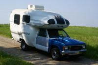
May I present the elusive S10 dually
I couldn't resist popping on one of the simulators..sweeet
Lots of work to do such as brake lines,sway bar, air bags and drive shaft but I'm feeling pretty inspired
-
Today started by running around to four different stores to track down a can of primer. Finally Auto Value found me a can and I made it back to the shop around noon
I used a contour gauge to get the general shape of the tube and started grinding away on my spindle sander
I ended up removing quite a bit of material to get it to fit
I leveled the tube and set the pinion angle
After a couple coats of primer it was finally ready to weld. I welded each side in two passes from the top down and let it cool down in between beads. It looked a little crappy where the two welds met but as they say, "If you can't be a good welder at least be a good grinder". One down and one to go
-
6 hours ago, jdemaris said:
Did you have any trouble with the crush-collar on the pinion? I bought three for mine before I could find one that was correct. Even then, I was amazed at how much torque it took to crush it. I had a 3/4 drive rachet with a three foot pipe on it to do the job.
I didn't remove the pinion just the nut. I marked it's location and took it off with an impact,replaced the seal,pinion nut and finally recrimped it with a chisel.
-
I started working on the spring perches this afternoon,
The first thing I needed to do was reprimand my security detail for sleeping on the job
Next up was to fabricate a jig for the leaf spring dowels. I started out with a straight piece of birch and laid out the holes. Once I got it right I added the offset pieces and finally cut out the center. Surprisingly it is accurate to within .25 mm
I cut off the old perch with a recip saw and started grinding away
Tomorrow I am going to pick up some weld through primer and see if I cant get one perch welded in place
-
11 hours ago, WME said:
If you aren't aware the E-brake cable may need some jiggling
Jiggling? I was thinking of spraying them down with some penetrating oil but I still need to figure out how to splice them into the S10 e-brake system. I have read that there are crimping tools available for boat rigging that will work but I haven't done a ton of research on it yet
-
I got the other side buttoned up today as well as the installation of a new pinion seal. Tomorrow I am going to start working on the spring perches
-
Good news/Bad news
Bad news; I had to work all weekend doing a side job for project fundraising which left me very little time for the rear end
Good news; The side job is done and the fundraising was enough to secure a set of Vantra's
Good news; My replacement spring perch showed up on Friday
Good news; I managed to get a little work done on the rear end tonight
-
9 hours ago, jdemaris said:
What happened to the original spring perches? (maybe I missed it somewhere in the posts).
I find using a spring-scale to set the bearings a waste of time and too subject to erroneous readings. In the end - all Toyota wants is zero end-play. No end-play and no to little preload. That's why in the Toyota manual - at the end - it says there should be no "axial play." So, it seems they are admitting that even with the spring-scale use - it may be wrong when done.
The original spring perches are still welded to the axle tube...but not for long
As far as setting the preload on the wheel bearings is concerned I followed the Toyota manual to the extent possible,right wrong or in between. I have come to realize that the guys that built whatever I'm working on know more about it than I do. Yes I am sure there are shortcuts (as with most things) but I am also sure I haven't worked on enough Toyota axles to know them.
-
15 minutes ago, WME said:
GUESS WHAT... somewhere there is a fella with a set of spring perches that look just like your set
lol, you're probably right. I am hoping I get to keep the wrong one so I can use it to set up my welder.
-
So far this week I have been able to pull apart the left side and get it cleaned up and painted. This side had a leaky wheel cylinder so the clean up was way more time consuming than the other side
My spring perches showed up today and one of them fit like a glove and the other..well,not so much. I have an email into the company,we'll see how they handle it
-
Thanks Linda, I'm painfully slow but thorough
Yesterday I ordered the replacement spring perches from Ruffstuff Specialties. They specialize in suspension parts for off-roaders. The perches will need to be moved inboard 1/2" per side as well as ground to fit the additional gusseting on the Toyota tube. One handy feature is the adjustable center hole which gives me a shot at getting the driveshaft to fit without additional work.
-
I had an hour to kill today so I popped the axle back in. The preload setting was kind of a pain with the new drum and shoes dragging a bit but I think I got it within spec. One interesting discovery was an axle seal I found on the axle itself.
This was odd because I had already taken one out of the tube. The maintenance guy at U-haul must have been hungover that day. At any rate one side down,one to go
-
I finally had a little time to work on the rear end last night. I managed to get the hub back together and installed. The only problem was the brake drum which was a little reluctant to fit over the hub. After a little sanding I got it to drop in place. Now I need to locate a spring scale to set the preload, then it's on to the other side
-
Made some progress today but not as much as I had hoped. I ended up drilling out my broken bolt in the e-brake cable housing and It took me a while to cobble together a fix for it.
The other thing that seemed to take forever was cleaning up the hub.....man that thing was filthy. It is now painted but not dry so I couldn't finish the right side
I did however get the new brakes installed
Before
After
-
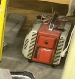
6 hours ago, jdemaris said:
What is the box-shaped thing with the Andreas Stihl color-scheme? Kind of looks like a generator. If so, I did not know they ever sold one.
That is the Great Grandfather of the EU series Honda generator. It is from the early to mid 70's and still runs like a Swiss watch. It is only a 400 watt unit but it is only as big as an Igloo lunchbox. One cool feature is the DC out so you can charge your vehicle batteries cordlessly. I haven't run across many things that are as handy
-
Not much time this week but at least I think I have all the parts together
Shoes
Drums
Wheel Cylinders
Hardware
Inner/Outer seals
Hub gaskets
Pinion seal
I started to pull apart the right side today. I got all the way down to the backing plate and gave it a good wire wheeling and a coat of paint. I managed to break a bolt for the e-brake cable mount but I think I can get it out. The bearings looked good so I am just going to repack and reinstall them.
Tomorrow I am going to try to get it back together
-
i also found an old picture of the original carbed 2.8
-
1 hour ago, jdemaris said:
I had a 1986 4WD S15 Jimmy for years with a TBI 2.8 and a 700R4. It ran fine for what it was. Got 19 MPG on highway runs. Sold it with 180K and engine ran fine, but yes - not a powerhouse. The reality is - I would not expect any engine that small to be powerful - at least not of that vintage. I went from that to a 1995 AWD Astrovan with the 4.3 and CPI injection and the 4L60E. It got a best of 18 MPG and is likely the worse piece of crap I ever owned, including the CPI fuel system. Never any huge mechanical issues other then the fuel injection. Many small problems - almost on a weekly basis.
When it comes to V8s - if I wanted one in an RV - I'd have something like a Roadtrek, or a coach-on-frame diesel. Not why I mess with little Toyotas and Datsuns. My main goal is ultimate fuel mileage for travellilng cross country with three people and a dog. I am kind of disappointed with the fuel mileage in my 1988 20 footer with the 2.4 EFI and auto trans. My 1978 Chinook with the 2.2 and 5 speed manual is MUCH better, but it is also MUCH smaller. I've got a dually full-floater in that. I can get 22 MPG with it and I wonder if it would do better is I'd left the original single-tire SF rear in it that it came with OEM.
That's a lot of power to give up for 1 MPG.... granted you had the worst version of the 4.3 ever made. If you get years made prior to and after their early vortec designs they are some of the most dependable engines GM ever made (at least in my opinion) which is why I chose to go through all of the work to convert my Mirage over to a fuel injected (TBI) 4.3 . I think they offer a nice blend of power/fuel ecomomy and dependability for an application such as this


Interior Paint/ Seat Recover and Rear Cargo Rack
in Improvement and Do-It-Yourself Projects you have done to Share!
Posted
It looks very comfy, nice job