WME Posted August 21, 2016 Share Posted August 21, 2016 If you can't be a good welder, be a good grinder....Works for me Quote Link to comment Share on other sites More sharing options...
Back East Don Posted August 22, 2016 Share Posted August 22, 2016 1 hour ago, WME said: If you can't be a good welder, be a good grinder....Works for me I fit this statement perfectly with everything except stainless with TIG. Easiest welding there is. Quote Link to comment Share on other sites More sharing options...
jjrbus Posted August 23, 2016 Share Posted August 23, 2016 On 8/21/2016 at 7:22 PM, WME said: If you can't be a good welder, be a good grinder....Works for me I used to be able to go around a pipe with a stick and it would look like a row of dimes. Now I can't hit the pipe, sad. Jim Quote Link to comment Share on other sites More sharing options...
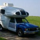
Motordome Posted August 26, 2016 Author Share Posted August 26, 2016 The last couple of days have been busy and the camper is now a little closer to being complete I started by using my wooden jig to locate the second perch Then welded it on I wanted to re-use the S10 shock mounts but this meant redrilling the ubolt holes to accommodate the Toyota ubolts. I plug welded the existing holes and then redrilled them with my drill press Sandblasted then painted the hardware Coated the housing with rust converter And in she went which was kind of a pain working alone but once I got it in place it dropped right on the spring dowels and the ubolts fit like a glove May I present the elusive S10 dually I couldn't resist popping on one of the simulators..sweeet Lots of work to do such as brake lines,sway bar, air bags and drive shaft but I'm feeling pretty inspired Quote Link to comment Share on other sites More sharing options...
Motordome Posted August 28, 2016 Author Share Posted August 28, 2016 I was working on the sway bar yesterday and my sister stopped by the shop and dropped off this book for me (she had no idea what I was working on) If i ever need to mass produce dually S10's this should come in handy Quote Link to comment Share on other sites More sharing options...
Motordome Posted September 3, 2016 Author Share Posted September 3, 2016 (edited) Working on the sway now, I welded some 3/16" plate to the back facing side of each shock mount to support the link bracket. Then I was able to reuse the Toyota mount after cutting off the bolt tabs. Everything then got blasted and painted The sway bar got blasted and a few coats of aluminum paint It should be dry tomorrow morning and I am hoping it will bolt right it. It shouldn't be a problem since I had it in and out about a thousand times during the mock up phase. Edited September 3, 2016 by Motordome Quote Link to comment Share on other sites More sharing options...
Motordome Posted September 4, 2016 Author Share Posted September 4, 2016 The installation went well. The links are not perfectly vertical but much closer than before. Ready for RV autocross Quote Link to comment Share on other sites More sharing options...
Motordome Posted September 6, 2016 Author Share Posted September 6, 2016 I started working on the drive shaft situation today. I manage to get the flange off of the Toyota DS which realllllly took an effort. I bolted it on to the pinion and this is what we have It's about 1 1/4" or 32 mm so it looks like a DS cut down is in order I can move the rear end back but not quite enough to make it all work. Besides that I think the tires are pretty well centered and I don't want to move them. One thing I have to figure out is the u joint set up. According to a chart I found the S10 uses a 1330 u joint but I haven't been able to dig up much info on the Toyota u joint, all I know is that it's a bit smaller. I did find this...... If this flange will bolt up then I believe I could use a stock S10 u joint On a positive note I was eyeballing the drive shaft angle and it looked fairly straight to me.....I was worried about the offset a little Quote Link to comment Share on other sites More sharing options...
Motordome Posted September 11, 2016 Author Share Posted September 11, 2016 I am looking at a couple different shops to do the driveshaft work so in the meantime I worked on my spare tire carrier this weekend. The original unit had a broken cable and I really don't like the way the design works with the camper body. I decided to start from scratch and ripped the old one out I found some 5/8" threaded rod to use for the mount so I was looking around for a large metal circle to use as a center retainer. I found an old 10" saw blade that had a broken carbide and as luck would have it it already had a 5/8" arbor hole. The blade was a heavy duty unit so the body was about an 1/8" thick. I broke off all the carbides and ground off the teeth. Once this was done I installed it in a jobsite saw and hit it with a grinder while it was running to shape it back to a decent circle. I welded up a 1/4" bar with a couple stubby handles. The center nut was replaced with a castle nut I covered the edge of the blade up with some fuel line with a center split and mounted it in place I still need to drill the rod for a cotter pin but it works pretty good. The weight of the tire provides enough friction on the retainer so you just spin the tire and it threads itself up and down. I will just need to keep the threads greased and it should work great. Quote Link to comment Share on other sites More sharing options...

Recommended Posts
Join the conversation
You can post now and register later. If you have an account, sign in now to post with your account.